FREE 1 to 3-Day Delivery on Orders $119+ Details

How to Install SkyJacker RockLock Front Sway Bar Assembly for 4-6 In. Lift on your Wrangler
Shop Parts in this Guide
IMPORTANT NOTES:
• Front bumper will need to be trimmed to allow for clearance of the new hub.
• Please refer to Parts List to insure that all parts and hardware are received prior to disassembly of vehicle. If any parts are found to be missing, contact your dealer as soon as possible.
• Note: Vehicles with Skyjacker's adjustable front track bar may need a new track bar relocation bracket. (See Page #4). The old design was a double sheer where the end link mounted between OE and Skyjacker's bracket. If the new bracket is needed, order part # 7146-B.
• This Sway Bar assembly is equipped with 2 sets of threaded end links. The longer 10" links are recommended for lifts 6-10". The Shorter 7 1/2" links are recommended for lifts 2-4".
Installation:
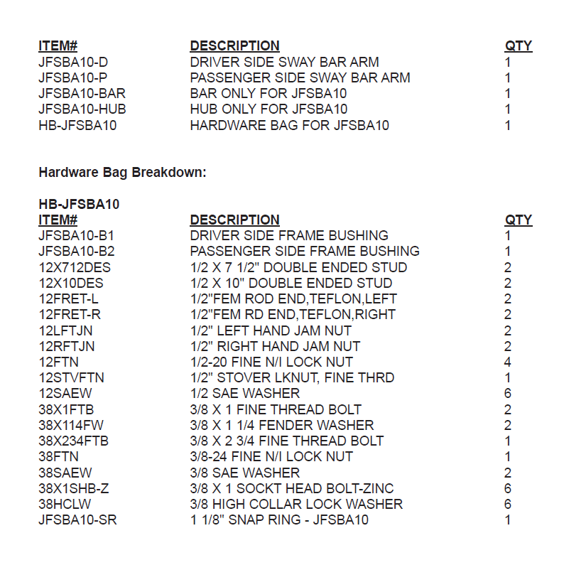
1. Park the vehicle on flat, level ground and set emergency brake. Disassemble the new RockLock hub. Attach the hub body to the driver side sway bar arm using the 3/8" socket head bolts with lock washers under the head. (See Photo #1)
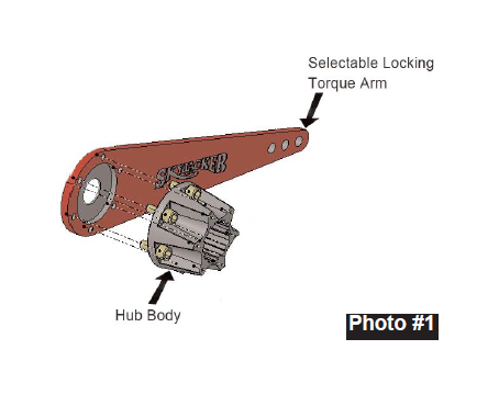
2. Locate the front tubular cross-member in the frame. Be sure the inside of the cross-member is free from burs. Install the new bushing on the driver side. (The driver side bushing will have the thicker head.) Install using a dead blow hammer. (See Photo #2).
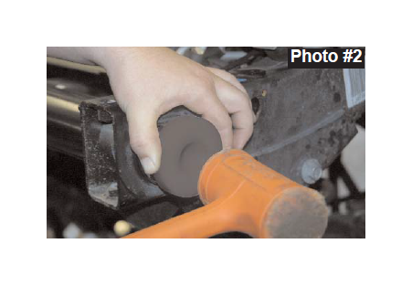
3. Insert sway bar from passenger side and through new driver side bushing. (See Photo #3). Drive the passenger side bushing over the sway bar and into the frame.
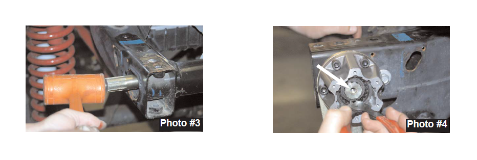
4. Install the driver side arm and hub assembly onto the splined sway bar. With gears installed, install the snap ring. Install snap ring onto groove in sway bar. (See Photo #4).
5. With Snap ring installed, install the 3/8 x 1" fine thread bolt and large fender washer into the end of the bar. (See Arrow in Photo #4). Tap the bar so that the driver side arm and hub assembly seat up against the frame bushing.
6. Install hub cap.
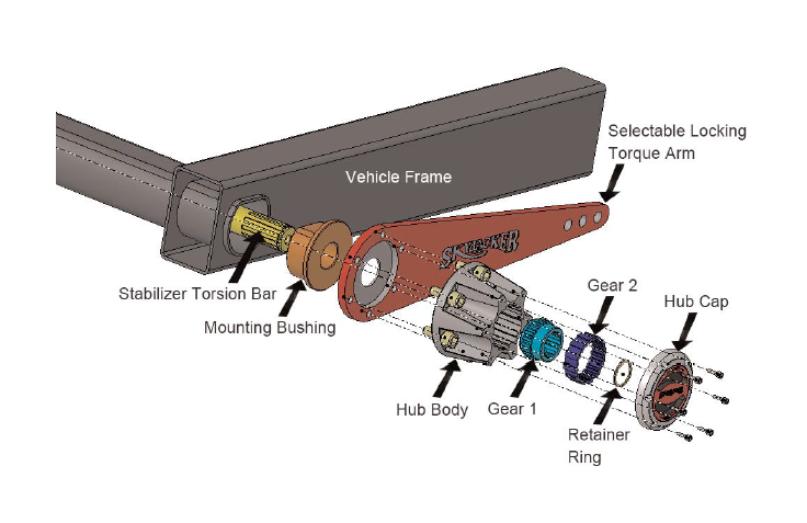
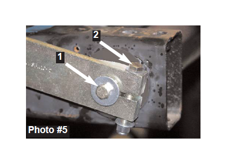
7. Attach passenger side arm. Install so that it is parallel with the driver side. Attach the arm to the end of the shaft using the 3/8 x 1" fine thread bolt and large fender washer. (See Arrow #1 in Photo #5)
8. Install the 3/8 x 2 3/4" fine thread pinch bolt with washers and nyloc nut. (See Arrow #2 in Photo #5).
9. This Sway Bar assembly is equipped with 2 sets of threaded end links. The longer 10" links are recommended for lifts 6-10". The Shorter 7 1/2" links are recommended for lifts 2-4"
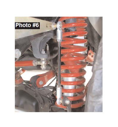
10. Assemble each end link with a 1/2" jam nut and left hand/right hand rod end. Attach to the oe location at the axle and the new sway bar arm using the 1/2" fine thread nuts and washers supplied. At the bottom, the location under the nut will not require a washer. (See Photo #6)
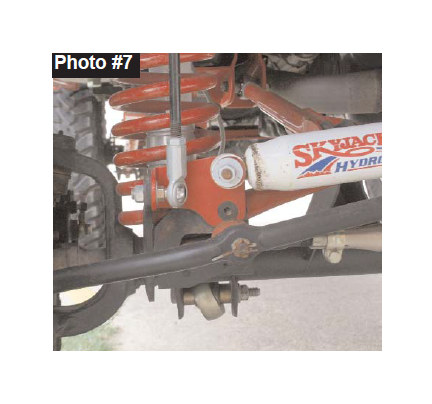
11. Vehicles equipped with a Skyjacker adjustable front track bar, will use the 1/2" stover nut at the bottom on the driver side. (See Photo #7) Note: Vehicles with Skyjacker's adjustable front track bar may need a new track bar relocation bracket. (Shown in Photo #7). The old design was a double sheer where the end link mounted between OE and Skyjacker's bracket. If the new bracket is needed, order part # 7146-B.
12. With end links installed, tighten the 1/2" jam nuts.
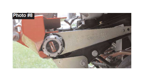
13. The sway bar arms should be level, if not slightly running uphill. This will ensure that at full travel, the arms will not flip toward the front of the vehicle. (See Photo #8).
Notes:
• If there is slack on the Driver side arm you will need to slide the whole assembly towards the passengerside. Then loosen passenger side arm slide towards frame to hold sway bar in that location.
• Each arm has 3 separate mounting locations for the end links. The location farthest from the front of the vehicle will be the softest setting. After driving, if this setting is too soft, the end link can be moved toward the front to provide a firmer setting.
• If the arms seem to be un-parallel, the outer gear on the hub can be clocked on the inner gear to help align.
• This kit is deigned for the hub to be in the locked (4x4) position while on-road, and un-locked (2x4) position for off-road.
• On vehicles with less lift, the end links can be shortened to allow for proper installation.
• After install is complete, check travel on suspension to ensure clearance on all parts.