FREE 1 to 3-Day Delivery on Orders $119+ Details

How to Install Artec Industries Under Armor - Bellypan Kit on your Wrangler
Shop Parts in this Guide
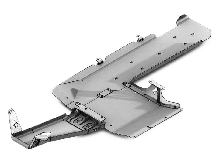
Thank you for your purchase of our Under Armor Kit designed to protect the underside of your JK Jeep Wrangler. All the pieces of this truss are designed to fit very closely to each other for a simple and precise assembly. If you have any questions that are not answered in these instructions, please feel free to contact us directly at sales@ artecindustries.com for assistance.
STEP 1. Unpack contents of shipment. Make sure that all of the parts required are included with your kit. If any items are missing, and packaging is damaged, KEEP ORIGINAL PACKAGING and contact us.
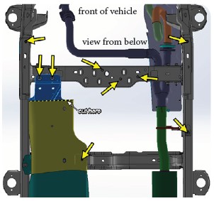
STEP 2. Using an 18mm socket, loosen the bolts as indicated in the following diagram and remove the OEM transfer case skid plate and exhaust skid. Using a cutoff wheel, trim the front of the gas tank skid on the indicated line and unbolt the two bolts from the crossmember. Discard this scrap piece of gas tank skid. Some of these bolt heads may be mangled from rocks so using a slightly larger socket or vice grips may be necessary.
STEP 2A. FOR BEST RESULTS, USE AN ARTEC HD CROSSMEMBER TO ACHIEVE A TOTALLY FLAT BELLY. If using an Artec HD Crossmember, uninstall the factory crossmember by supporting the transfer case with a jack or straps. Unbolt the internal bolts in the crossmember holding the transfer case. Unbolt the bolts holding the crossmember to the frame and remove the factory crossmember. Install the Artec HD Crossmember using the reverse method.
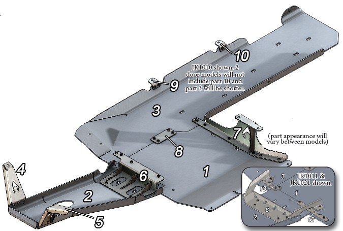
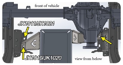
STEP 3. Using the included 1/2” (and 5/8” for JK1010/ JK1020) hardware, bolt parts 4 & 5 to the brackets holding the motor mounts in the indicated holes. HAND TIGHTEN ONLY. Drooping the axle from the chassis will ease installation. Do not attach part 2 yet.
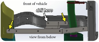
STEP 4. Locate the upper crossmember above the factory transfer case skid plate hole on the gas tank. Using the long 1/2” hardware, lightly bolt the upper bolt hole of part 7 to the existing crossmember hole. Bolt (hand tight) the lower hole to the factory gas tank skid. Using a marker, indicate a drill location on the crossmember. Remove part 7 and drill with a 1/2” bit through both sides of the crossmember. Do not drill into the body. Reattach part 7 using the two top holes, not the lower gas tank hole.
STEP 5. Attaching part 6 is different between the models. See below for model specific instructions.
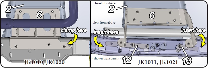
For JK1010/JK1020 automatic transmissions, place flanged section on top of the removable JK crossmember and align the 4 holes with the slotted holes in the crossmember. Use a clamp where indicated to hold part 6 to the crossmember. Lift part 2 into position and bolt (hand tight) part 2 through the crossmember to part 6 using the long flat head bolts. The center hole under the crossmember on part 2 uses either the factory M12 bolt (if using factory crossmember) or a 3/8” short flat head bolt (if using Artec HD crossmember).
Manual transmissions will require popping out the three press nuts under the transfer case mount bolts and running the transfer case bolts through the holes. This will place part 6 in between the t-case mount and the crossmember. Contact us if you have a manual trans for extra pieces and tech.
For JK1010/JK1020, place part 6 up and over the exhaust as shown. To temporarily hold part 6 in place either clamp or place part 13 underneath the crossmember, and using the empty hole, run a long 3/8” bolt through and up to the passenger side flange with press nut. Lightly tighten this to allow you to lift part 2 into place. Once in place, fasten part 2 to the crossmember using the factory M12 bolt (3/8” flat head bolt if using Artec HD crossmember). Unbolt part 13 and insert parts 12 and 13 into the crossmember as shown aligning the press nuts with the holes in the crossmember and part 2.
Fasten (hand tight) together parts 4 and 5 using hex head 3/8” bolts, nuts and washers. Using 3/8” short flat head bolts, fasten (hand tight) all the remaining holes in part 2 to part 6.
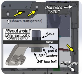
STEP 6. To install the transfer case skid (part 1), place part on frame and crossmember. Using the factory M12 bolts, fasten in the indicated locations. Using a marker, indicate the drill holes shown here and then remove part 1. Drill holes with 17/32” drill bit and install rivnuts using the method shown here. Reinstall part 1 and fasten (hand tight) all hardware including parts 7 and 8.
STEP 7. To install the gas tank skid (part 3), remove the 2 factory nuts holding the gas tank skid to the frame. Place parts 9 and 10 in their corresponding locations (shown on front page) and fasten (hand tight) using the factory nuts again. Place part 3 on frame and attach to parts 8, 9 and 10 and on the factory crossmember using correct hardware. Fasten parts 1, 3 and 7 together using the long 3/8” flat head bolt and thread a nut and washer on top of the factory M12 nut on the inside of the factory gas tank skid.
STEP 8. With part 3 in place, drill 3/8” holes into the factory gas tank skid in the 3 locations remaining on part 3. Take care not to drill into the gas tank. Fasten using hex bolts, hex nuts, and washers.
STEP 9. Ensure that all bolts have been hand tightened and no extra hardware remains. Proceed to tighten each bolt securely with tools using BLUE LOCTITE to ensure the bolts stay tight. Enjoy your ARTEC UNDER ARMOR.